Industry-first SAE J1939 multiplexing system controlled mobile hydraulic AC power generator systems.
SAE J1939 vehicle multiplexing systems
Smart Power Systems improves mobile power generation by integrating electronic control into a vehicle with an SAE J1939 multiplexing system and adding onboard diagnostics with event recording. Electronic control enables precise frequency output by controlling fluid flow through a hydraulic motor, ensuring a constant frequency output. Automated control features protect the system from conditions outside its designed operating parameters that may cause damage. The electronic controlled Multiplexing Interface Module communicates operation parameters in SAE J1939 approved format for integration with vehicle multiplexing. This paper describes the design and features of electronic controlled hydraulic generators and how SAE J1939 has expanded the system’s functionality while making operation more straightforward for the user.
What is Multiplexing?
Multiplexing, or muxing, is a way of sending more than one indicator or stream of statistics over a communications hyperlink at an equal time in the structure of a single, complicated signal. Multiplexing is technique networks use to consolidate a couple of alerts. Including digital or analog – into a single composite sign transported over a frequent medium, such as a fiber optic cable or radio wave. When the composite sign reaches its destination, it is demultiplexed. The character indicators are restored and made handy for processing.
Hydraulic generator J1939 vehicle multiplexing systems
Hydraulic generator systems need to range from 5.5kW through 30kW continuous 120VAC/240VAC clean power outputs. The primary usage of these systems is on fire and rescue apparatus, to power perimeter and scene lighting, extrication tool pumps, smoke ejector fans, and various other equipment. Other applications for these systems include pipeline inspection trucks, welding/ service trucks, mobile communications vehicles, marine, military, and other mobile equipment. Typically hot air recirculation (overheating) reduces generator output power-making capability. To solve the overheating problem (See Figure 1), an exclusive top mount generator design exhausts hot air straight up, eliminating hot air recirculation.
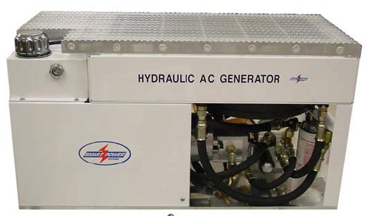
Figure 1: Smart Power® HR Series Top Mount Tray Assembly Tray
Each system includes an efficient hydraulic fluid cooling system to ensure the system temperature remains well below the operating limits of the components. Added larger than the critical cooling system operates in higher ambient temperature environments while enhancing long-term reliability.
Why Multiplexing?
The transmission medium is used to ship the sign from sender to receiver. The medium can solely have one signal at a time. Suppose there are more than one indicators to share one medium. In that case, the medium has to divide, so every sign is given some element of the on-hand bandwidth. For example: If there are 10 alerts and the bandwidth of the medium is 100 units, then the 10 unit is shared by way of every signal. When more than one alerts share with the frequent medium, there is an opportunity for collision. Multiplexing idea is used to keep away from such collision.
SAE J1939 control enables advanced features such as expanded control, diagnosis, and operator feedback.
Typically hydraulic systems rely on fluid flow (GPM) to maintain frequency and voltage. As hydraulic fluid changes temperature, viscosity changes affect flow rate, affecting voltage output.
In addition, as load (watts) is added to the generator, the voltage increases. The hydraulic fluid flow is set to compensate but often falls short, causing the low voltage at full rated load. As ambient temperature increases, more significant losses in efficiency occur, creating the following issues:
1. Low voltage
2. Overheating
3. Generator component damage
Improvements are described herein by adding electronic control in addition to multiplexing.
Goals for the Hydraulic generator
Mobile power generation operates with unique requirements, including minimal space, widely varied environmental conditions, and high demand for zero downtime, especially in the fire and rescue industry applications.
The goals of the electronically controlled Hydraulic generator design are:
1. Superior reliability through automated features
2. Low downtime through advanced diagnostics
3. Superior performance through high-technology control and hydraulic fluid cooling systems
4. Ease of use through multiplexing integration
5. Space savings through compact design
6. Reduced installation times
7. Exceed 120°F ambient temperature operation
Control J1939 vehicle multiplexing Hydraulic generator systems
Since early 2003, we have equipped all electronic controlled generators with a unique proprietary electronic control system that optimizes performance and prevents generator and vehicle equipment damage. Including a multiplexing interface module, which converts all communication to SAE J1939 for integration into the vehicle’s centralized multiplexing system.
Multiplexing Interface Module
As the electrical complexity of vehicles increases and multiplexing systems become the standard method of wiring. We developed SAE codes for mobile generator systems. The electronically controlled system offered the first opportunity as they didn’t exist prior.
Multiplexing Interface Module is a separate component in a NEMA 4 enclosure.
The electronic controlled Multiplexing Interface Module is a separate component in a NEMA 4 enclosure of the hydraulic generator system, capable of being remote mounted at a location convenient to the multiplexing bus wiring of the vehicle. We provide two connectors, one giving power, ground, and communications, and the other a standard J1939 stub connector. See Figure 2.
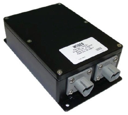
Figure 2: Multiplexing Interface Module
The interface module kit comes with a wiring harness 15′ in length allowing for mounting within 15′ of the generator tray assembly.
Broadcast Messages of the J1939
After successfully claiming an address, the module will begin broadcasting its periodic messages. There are two periodic messages, each broadcast once per second. These are “Generator Output” and “Generator Status.” The Generator Output message provides voltage, frequency, current, and operating temperature information about the generator. The Generator Status message includes information: whether the generator is running, could be started, the status of hydraulic pressure, the operating mode, the number of active alarms, whether an active alarm will cause a shutdown, and the total working time on the generator. The J1939 standard SLOTs (Scaling, Limit, Offset and Transfer function) expresses all values. Ascencioné® Industry Firsts document that includes the First SAE J-1939 multiplex Genset system; E-One, Pierce®
J1939 electronic control system
All information available through the generator’s standard electronic control system is available through the J1939 interface. Including voltage, frequency, current draw on lines 1 and 2, number of hours on generator, number of hours on a filter, system temperature, model name, kW output size, system warnings for overheating, overload, cold fluid, low oil, service reminders, display calibration, alarms, shutdowns, overrides, and real-time troubleshooting steps. Complete diagnostics with event recording is also standard and available through the multiplexing system. This system enables the ability to view a record of the entire operating history. The record includes but is not limited to • highest recorded voltage • highest recorded frequency • highest recorded current • highest recorded temperature • the number of over-temperature shutdowns • the number of over-temperature shutdowns overrides • hours at over-temperature • the number of overcurrent faults • hours run at overcurrent • hours on a filter • valve faults • fan faults •temperature sensing faults.
Standard Display and Features
All systems are available without the multiplexing interface module for users who do not have or desire a fully multiplexed vehicle.
Command and Control Center (CCC)
The user interface display is the Command and Control Center (CCC), which is included even with systems equipped with the multiplexing interface module. The National Fire Protection Association (NFPA) requires a display within sight of the distribution panel on fire and rescue apparatus. The standard CCC’s small size and low cost make it a much more suitable display than adding another full multiplexing display at this location. The CCC is ruggedized for the environment and features a compact size, sealed, and 100% solid-state design. Smart Touch® non-contact switching eliminates failures caused by water, mechanical damage, and operational problems caused by bulky gloves. See Figure 3. Multiple displays can be connected to the system using a simple y-splitter and additional wiring harness.
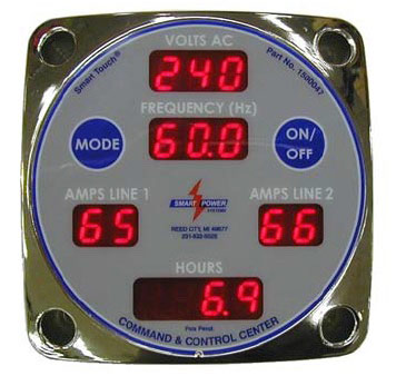
Figure 3: Standard Command and Control Center Display
Electronic Control Unit
The Electronic Control Unit, or ECU, is located in the tray assembly and is the system’s brain. The ECU optimizes performance to ensure cleaner frequency output. It automates generator functions to prevent damage to the generator and vehicle equipment. This protection starts from the second you press the “On” button by slowly increasing the fluid flow to the hydraulic motor, then regulating it to maintain exactly 60Hz. Commonly referred to as the “soft-start” feature eliminates shock to the generator components and the vehicle powertrain. The exact frequency regulation allows more sensitive equipment, such as battery chargers, communication equipment, and computers, without fear of damage. Once the system is running, the ECU continuously monitors all aspects of the generator. Monitoring ensures excessively cold fluid temperatures are not used while running, which can cause damaging electrical spikes. Also, monitoring ensures excessively hot fluid temperatures. Hot fluid can cause pump and motor damage due to insufficient lubrication or too much load, which can cause damage to the electrical system and vehicle wiring. The system will also ensure that running with low fluid levels or other conditions that could lead to premature failure are not allowed. Service reminders instruct the user when the hydraulic fluid filter needs replacement and ensure preventative maintenance is not overlooked as the only service required.User Advantages with J1939 Multiplexing
While all features required for a highly reliable and fully functional generator system are provided with the standard generator package. Many features are highlighted or added through the multiplexing interface module.Easy operation with a multiplexing display
Whether using the standard CCC display or a vehicle multiplexing display, turning the generator on and off is a simple one-touch operation. The additional buttons and display space of a multiplexing display such as Weldon’s V-MUX Vista III Interface Module/Display enable the even easier operation. Along with other display capabilities that become difficult with the limitations of an LED readout. For example, accessing the diagnostics through the CCC requires a unique 5-step sequence using the two touchpad buttons. While not difficult, the multiplexing display can reduce that to a one-touch step. In addition, accessing the generators option menu requires the operator to hold the mode button for ten seconds. Additional buttons available on a multiplexing display reduce to a one-touch step. See Figure 4 for an example layout of the buttons on a multiplexing display.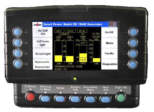
Figure 4: Generator Screen on Multiplexing Display
Graphical Interface Multiplexing
All generator operating information is available through the CCC display. Still, the full-color screen of a multiplexing display adds additional capability, which can provide the user with a complete understanding of the current condition of the generator. For example, if the generator’s load on line 1 is currently 41 amps, it will be displayed in the “AMPS LINE 1” block. If the system rates to 10,000 watts, the user may not realize that they only have 1 amp left before reaching the total rated capacity. The 41 amp readout can show over a bar graph showing how much usage is rated load on the multiplexing display. Another readout states explicitly that the generator was currently operating at 98% of its full rated load. See Figure 4.Plain English Messages with the Multiplexing Display
The information displayed through the CCC may not be as understandable to a user unfamiliar with the system’s operation. The CCC will show a hot oil condition as “OIL HOT 185°F”. See Figure 5.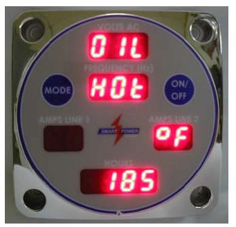
Figure 5: Command and Control Center Overtemperature Readout
That same warning displayed on a multiplexing display has the additional space to read, “WARNING – System Overtemperature.” It even continues with real-time troubleshooting steps the user can take to remedy the problem. See Figure 6. This additional information can mean the difference between having electrical power and not having electrical power. In the fire-rescue industry, it can mean life and death.
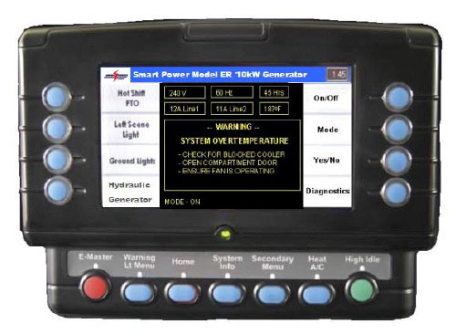
Figure 6: Generator Overtemperature Warning on Multiplexing Display